logo
NOTICE:  This is the new PunchCAD forum. You should have received an email with your new password around August 27, 2014. If you did not, or would like it reset, simply use the Lost Password feature, and enter Answer as the security answer.
Welcome Guest! To enable all features please Login or Register.

Notification

Icon
Error

Options
Go to last post Go to first unread
mlochala  
#1 Posted : Tuesday, September 6, 2011 5:16:17 PM(UTC)
mlochala

Rank: Senior Member

Joined: 9/1/2008(UTC)
Posts: 140

Hello everyone! I haven't posted anything in a while but I wanted to share this latest project with you.

I'm a do-it-yourself kind of guy. So, recently, when my transmission went out on my car, I decided that this time I would rebuild it myself. I also realized that I'm lacking in a few necessary tools to do this kind of work, namely a transmission jack. So, I got to thinking.....and drawing with ViaCAD. And, here's what I came up with.

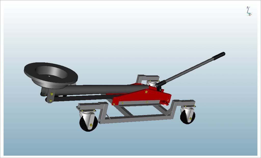
This is a design for converting a normal two ton floor jack into a handy transmission or accessory jack. I started by reverse engineering a cheap MVP floor jack that I had in my garage and then digitally converting it into a handy jack capable of lifting a slightly lighter load (500lbs, give or take) but with a much wider range of lift. Originally, the floor jack had only about 8" of lifting range. So, I redesigned it to have about 24" of lifting range, more than enough to remove a transmission from a car.

Here's what the original jack looks like:

UserPostedImage

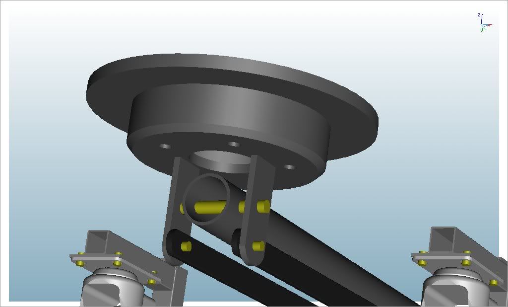
Another thing I decided to do to simplify things is to recycle an old brake rotor to use for the head of the jack. The 11" rotor provides more than enough square inches required for a stable lift.

ViaCAD Pro wasn't just useful for constructing a 3D model of my idea, but even before I began modeling the actual jack, I started by using some very simple line drawings to work out the geometry challenges. ViaCAD Pro was the perfect tool for this.

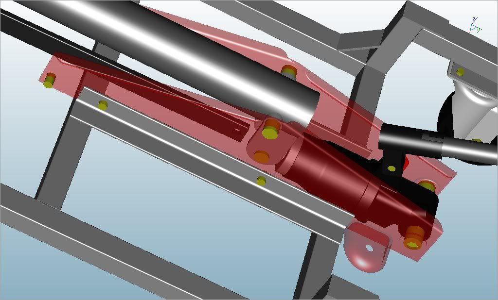
Now, this is a very simple model. I did a very quick simple model of the components that I planned to re-use from the original jack, including the pump, the handle, the ram and the frame. I also modeled some swivel castors that I purchased from Harbor Freight. In place of bolts, I just did some quick extrusions of appropriately sized circles.

Here's the result:

UserPostedImage

UserPostedImage

UserPostedImage

I have actually built this jack over the weekend and it turned out great. As soon as I can, I will upload pictures of the actual product. ViaCAD has become one of the most important tools I have!
zumer  
#2 Posted : Tuesday, September 6, 2011 7:12:38 PM(UTC)
zumer

Rank: Senior Member

Joined: 11/4/2007(UTC)
Posts: 515

Was thanked: 1 time(s) in 1 post(s)
Nice work, and nice execution, but I'm dubious about the square tube necks that the castors are mounted on. It'd pay to reinforce them with a couple of gussets.
zumer attached the following image(s):
gussets.png (16kb) downloaded 5 time(s).

You cannot view/download attachments. Try to login or register.
mlochala  
#3 Posted : Wednesday, September 7, 2011 10:42:23 AM(UTC)
mlochala

Rank: Senior Member

Joined: 9/1/2008(UTC)
Posts: 140

Hey Zumer, thanks for the reply!

I agree, I was somewhat concerned too. But, I had limited time and materials to use so I tried that first and loaded it to the hilt. It did well, with almost no flex as is. I ended up using some 1-5/8 unistrut instead of the 1" square tubing.

I actually put the jack to use yesterday evening when I removed the transmission from my Toyota T100. It worked very well, but I do see some room for improvement. One thing I overlooked in my design was balance. When the transmission is resting on the jack, the back wheels get very light. So, as soon as I get the chance, I'm going to extend the front wheels another 6" and I have decided to add some more support just to be safe. Also, I will add some latch points for a safety strap or chain.
Tim Olson  
#4 Posted : Wednesday, September 7, 2011 10:47:26 AM(UTC)
Tim Olson

Rank: Senior Member

Joined: 2/2/2007(UTC)
Posts: 5,447
United States

Was thanked: 499 time(s) in 353 post(s)
Awesome Mark!

Tim
Tim Olson
IMSI Design/Encore
mlochala  
#5 Posted : Wednesday, September 7, 2011 11:07:01 AM(UTC)
mlochala

Rank: Senior Member

Joined: 9/1/2008(UTC)
Posts: 140

Here's the jack being used for the first time:

UserPostedImage

Here's a closeup. Don't look too closely at the welds...I was having fits with my contact tip in the nozzle. When I have finished modding it, I will clean it up and paint it.

UserPostedImage
mlochala  
#6 Posted : Wednesday, September 7, 2011 11:08:00 AM(UTC)
mlochala

Rank: Senior Member

Joined: 9/1/2008(UTC)
Posts: 140

Sorry about the big pictures. I've tried reducing their size, but they keep coming back too large. ?????
ZeroLengthCurve  
#7 Posted : Wednesday, September 7, 2011 3:27:17 PM(UTC)
ZeroLengthCurve

Rank: Senior Member

Joined: 5/15/2008(UTC)
Posts: 987

Thanks: 19 times
Was thanked: 35 time(s) in 24 post(s)
That's great creativity and repurposing of parts.

You might want to label your pics and declare you are placing this into the public domain under some convenient license just to make sure it is now duly forced into "prior art" status so no one re-does your work and then patents it and prevents even YOU from doing further work on YOUR work. It would be too expensive to patent unless you could sell 10s of thousands of them.

Not saying the regulars here are going to misappropriate your ingenuity, but any site with creative ideas in it is a harvesting zone for lurkers out only to scarf up ideas and put them into play faster than you since you may lack resources and may not even suspect someone is about to Hail Mary you.

As for the drawing and your calculations, did you use the 3D solids and CGs and Moments facilities in VC/VCP? If not, you may want to do so before you invest in your upgraded lift jack. If you do, you can rotate the pump and moving parts about the center vertical axis and add mass incrementally. Chart it or graph it and then you can determine now much weight is ranging out past or dangerously close to a tipping point when the apparatus is being pushed or towed or taken through a turn. If VCP had some rudimentary movement measurements, that might be possible to calculate for slow, but moved objects like yours. I'm assuming that if you or anyone else build your device, there might be sloped floors somewhere and a non-careful user might find out after tipping their object off to the floor.

The casters/wheels might have some verrrry small (maybe negligible?) amount of compression, which you may or may not want to look at in the event you find it worthwhile to do this as side work. In some home garages or shops you or others might wear down the wheels and it might later factor into safe areas vs tipping points...

If you DO decide to make or sell these, the scary part will be the potential litigious suits risk. If you don't get a lawyer and don't overengineer it to stave off suits and complaints, you may regret selling these. Still, it's cool of you to show what you did and that you did it with VC.

Just some ideas before I forgot them ... not that you haven't already worked these out.

Nice repurposing.
mlochala  
#8 Posted : Wednesday, September 7, 2011 5:27:53 PM(UTC)
mlochala

Rank: Senior Member

Joined: 9/1/2008(UTC)
Posts: 140

Hey ZLC, thanks for the reply! Thanks for sharing the ideas. They are all great.

No, I just built this for myself for limited use. If I were building to sell, I'd have a lot more safety features built in.

Quote:
As for the drawing and your calculations, did you use the 3D solids and CGs and Moments facilities in VC/VCP?


Actually I didn't, but that is a very good idea. I should have done that really. What I did prior to doing the model was make some very simple line drawings and rotated those to simulate the motion of the jack arm and the head. Then, I just used those dimensions in mechanical leverage formulas to make sure I wasn't overloading the hydraulic pump and to find out what the new maximum capacity was.
Users browsing this topic
Guest
Forum Jump  
You cannot post new topics in this forum.
You cannot reply to topics in this forum.
You cannot delete your posts in this forum.
You cannot edit your posts in this forum.
You cannot create polls in this forum.
You cannot vote in polls in this forum.