logo
NOTICE:  This is the new PunchCAD forum. You should have received an email with your new password around August 27, 2014. If you did not, or would like it reset, simply use the Lost Password feature, and enter Answer as the security answer.
Welcome Guest! To enable all features please Login or Register.

Notification

Icon
Error

Options
Go to last post Go to first unread
friolator  
#1 Posted : Saturday, November 9, 2019 12:06:00 PM(UTC)
friolator

Rank: Guest

Joined: 10/29/2019(UTC)
Posts: 27

Thanks: 3 times
Was thanked: 1 time(s) in 1 post(s)
I've got another part I'm having a hard time with, as far as making holes. I need to make a model of this part. I've created a simple 32mm x 3mm cylinder, then a 16mm x 10mm cylinder on top of that. I've used the Add Solid tool to make them one piece. No matter what I try, I can't get a hole to go through both.

When I use push/pull, it only goes through the smaller cylinder, and ends when it hits the face of the 32mm flange at the base.

When I use the Hole Tool (creating a point on the face of the small cylinder at the center, selecting the face of the cylinder as the face into which the hole goes, then option-clicking on the point), I get two dialog boxes:
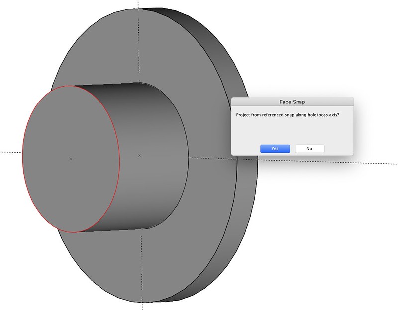
dialog 1

And when I click Yes, I get:

dialog 2

How does one do this? I'd think that by using Add Solid to merge the two solids into one, I would be able to put a hole straight through the new object, but I can't.

Edited by user Saturday, November 9, 2019 12:06:56 PM(UTC)  | Reason: Not specified

L. Banasky  
#2 Posted : Saturday, November 9, 2019 1:31:27 PM(UTC)
L. Banasky

Rank: Senior Member

Joined: 2/16/2007(UTC)
Posts: 596

Thanks: 138 times
Was thanked: 139 time(s) in 99 post(s)
Are your snaps enabled for center, endpoint quadrant, etc.
You should have no problem with this.
I don't think Push-Pull is the right tool, and a point is not
needed, might be the problem.
I would always use the hole tool, should work for this,
see enclosed files.
Larry

Edited by user Saturday, November 9, 2019 4:50:15 PM(UTC)  | Reason: Didn't see your part, added Hub.

File Attachment(s):
Hole.sfx (17kb) downloaded 1 time(s).
Hub.sfx (30kb) downloaded 1 time(s).
L. Banasky attached the following image(s):
Simple Hole.jpg (69kb) downloaded 2 time(s).
Hub.jpg (71kb) downloaded 1 time(s).

You cannot view/download attachments. Try to login or register.
friolator  
#3 Posted : Saturday, November 9, 2019 6:43:41 PM(UTC)
friolator

Rank: Guest

Joined: 10/29/2019(UTC)
Posts: 27

Thanks: 3 times
Was thanked: 1 time(s) in 1 post(s)
I'll have to try it again on Monday when I'm back in the office. I spent about an hour this morning trying a bunch of different ways to make it work. I definitely had snaps enabled for center, endpoint, midpoint, on face, etc. Maybe the issue is using a point.
L. Banasky  
#4 Posted : Sunday, November 10, 2019 6:17:03 AM(UTC)
L. Banasky

Rank: Senior Member

Joined: 2/16/2007(UTC)
Posts: 596

Thanks: 138 times
Was thanked: 139 time(s) in 99 post(s)
The point shouldn't matter, but if the hole is on center,
the point would not really be needed.
The four holes can be added using a circle and selecting the quadrants.
Larry
L. Banasky attached the following image(s):
Circle.jpg (46kb) downloaded 0 time(s).

You cannot view/download attachments. Try to login or register.
friolator  
#5 Posted : Monday, November 11, 2019 7:56:02 AM(UTC)
friolator

Rank: Guest

Joined: 10/29/2019(UTC)
Posts: 27

Thanks: 3 times
Was thanked: 1 time(s) in 1 post(s)
Ok, so I just tried this again in a brand new project. I made a 32mm x 3mm cylinder, and made a 16m x 10mm cylinder centered on the face of the wide one, then used Add Solids to merge them together. I selected the hole tool and clicked on the face of the small cylinder. Then I clicked on the center point. And I continue to get the "Face containment cannot be determined" dialog, with no hole. If I select the entire cylinder, I get the "Project from referenced snap along hole/boss axis?" (YES) then "Inconsistent face-body relationships"

I did however, get it to work. I think the problem is that when you select the Hole tool, the parameters you set across the top of the screen assume a countersunk hole, and the settings I had for the countersink were impossible for the object I'm making. The issue here is that you can't turn off countersinking in that part of the interface, and unless I'm wrong, there's no way to do so until you can get to the hole in the Inspector (which you can't do until there's a hole, which you can't make with the settings I had). Once I managed to get a hole through the thing with different countersink settings, I was able to change the parameters in the Inspector and get what I was looking for.

Why can't you turn off countersinking when creating the hole in the first place? Or am I missing something where I can see all the parameters you can see in the inspector, before a hole is created?

Thanks!
luk72  
#6 Posted : Monday, November 11, 2019 10:21:59 PM(UTC)
luk72

Rank: Member

Joined: 10/17/2014(UTC)
Posts: 51

Was thanked: 15 time(s) in 9 post(s)
https://www.youtube.com/watch?v=UHdEUN1ijeY

Enjoy!

Edited by user Monday, November 11, 2019 11:43:09 PM(UTC)  | Reason: Not specified

thanks 3 users thanked luk72 for this useful post.
GARLIC on 11/12/2019(UTC), L. Banasky on 11/12/2019(UTC), MPSchmied on 11/16/2019(UTC)
murray  
#7 Posted : Thursday, November 14, 2019 11:35:18 PM(UTC)
murray

Rank: Senior Member

Joined: 9/24/2014(UTC)
Posts: 373
Australia

Thanks: 8 times
Was thanked: 104 time(s) in 85 post(s)
This is Shark V8, its constraints and patterns are in VCP V11. A revolved profile, constrained parameters through variables palette, hole and hole pattern parameters in inspector. It's a doddle. Initial hole tool properties are in the program header.

Edited by user Thursday, November 14, 2019 11:47:14 PM(UTC)  | Reason: Not specified

murray attached the following image(s):
constraintsPatterns.PNG (104kb) downloaded 8 time(s).

You cannot view/download attachments. Try to login or register.
friolator  
#8 Posted : Friday, November 15, 2019 7:28:55 AM(UTC)
friolator

Rank: Guest

Joined: 10/29/2019(UTC)
Posts: 27

Thanks: 3 times
Was thanked: 1 time(s) in 1 post(s)
Originally Posted by: luk72 Go to Quoted Post
https://www.youtube.com/watch?v=UHdEUN1ijeY

Enjoy!


Thanks. But what I'm not understanding is why my hole tool always comes up with the countersink settings enabled. If you look at the bar across the top of the program, in your video, you see there is no countersink setting. In mine, it's always there. So I have to create the hole with a countersink, then select it and go into the inspector to make it a simple hole.

How can I make it come up with the parameters I want from the start? That is, no countersink?
UGMENTALCASE  
#9 Posted : Friday, November 15, 2019 1:19:08 PM(UTC)
UGMENTALCASE

Rank: Senior Member

Joined: 3/21/2017(UTC)
Posts: 945
Man
United Kingdom

Thanks: 46 times
Was thanked: 298 time(s) in 203 post(s)
Do you not have another little toolbar that pops up when you select hole? It has 3 options in it, normal, c/bore and c/sink. It might be hidden behind something else you have on screen?
murray  
#10 Posted : Friday, November 15, 2019 4:38:55 PM(UTC)
murray

Rank: Senior Member

Joined: 9/24/2014(UTC)
Posts: 373
Australia

Thanks: 8 times
Was thanked: 104 time(s) in 85 post(s)
In all of my punchcad installs, windows, the data box that says countersink in the header is a flyout option box; click on it and it flies out with the expanded options. The other options are plain and counterbored.

Edited by user Friday, November 15, 2019 4:43:25 PM(UTC)  | Reason: Not specified

friolator  
#11 Posted : Saturday, November 16, 2019 7:08:03 AM(UTC)
friolator

Rank: Guest

Joined: 10/29/2019(UTC)
Posts: 27

Thanks: 3 times
Was thanked: 1 time(s) in 1 post(s)
Originally Posted by: murray Go to Quoted Post
In all of my punchcad installs, windows, the data box that says countersink in the header is a flyout option box; click on it and it flies out with the expanded options. The other options are plain and counterbored.


I don't know what a "flyoout option box" is. here's what I'm seeing:

1) Select the hole tool
2) Click on face where the hole goes
3) The bar across the top of the screen shows parameters for the hole to be made. these let you choose the type of hole and the plane, as well as text entry boxes for Depth, Diameter, Draft Angle, Sink, Sink Angle, Drill point. see attached.

These are always the same. there is no way to NOT have a countersink as far as I can tell.

Once the hole is made I can select it and go into the inspector, where I can change it to a simple hole. I've just done this on a complicated part that has about 50 holes, which meant post-editing 50 holes to remove countersinks.
friolator attached the following image(s):
Screen Shot 2019-11-16 at 7.55.41 AM.png (22kb) downloaded 2 time(s).

You cannot view/download attachments. Try to login or register.
MPSchmied  
#12 Posted : Saturday, November 16, 2019 8:41:25 AM(UTC)
MPSchmied

Rank: Guest

Joined: 4/9/2017(UTC)
Posts: 503
Man
Germany

Thanks: 262 times
Was thanked: 130 time(s) in 100 post(s)
Why you dont just use the simple hole tool?
MPSchmied attached the following image(s):
Zwischenablage02.png (20kb) downloaded 8 time(s).

You cannot view/download attachments. Try to login or register.
OS: Windows 10 | CPU: AMD Ryzen 7 2700 | RAM: 32 GB | Graphic: AMD Radeon RX Vega 56 | Shark FX 9 Build 1162 | Unit: mm
perry  
#13 Posted : Saturday, November 16, 2019 9:48:04 AM(UTC)
perry

Rank: Guest

Joined: 11/16/2019(UTC)
Posts: 47

Thanks: 6 times
Was thanked: 5 time(s) in 3 post(s)
Originally Posted by: MPSchmied Go to Quoted Post
Why you dont just use the simple hole tool?


Wait - so the icon in the upper left corner of the screen is a button that brings up options? I had no idea. I don't have ViaCAD installed on this machine, but is that in Pro v11, or is that a SharkCAD thing?
MPSchmied  
#14 Posted : Saturday, November 16, 2019 10:59:17 AM(UTC)
MPSchmied

Rank: Guest

Joined: 4/9/2017(UTC)
Posts: 503
Man
Germany

Thanks: 262 times
Was thanked: 130 time(s) in 100 post(s)
Originally Posted by: perry Go to Quoted Post

Wait - so the icon in the upper left corner of the screen is a button that brings up options? I had no idea. I don't have ViaCAD installed on this machine, but is that in Pro v11, or is that a SharkCAD thing?
No this is no SharkCAD Thing, this is a common thing for Shark and ViaCAD and all versions.

Edited by user Saturday, November 16, 2019 11:00:30 AM(UTC)  | Reason: Not specified

OS: Windows 10 | CPU: AMD Ryzen 7 2700 | RAM: 32 GB | Graphic: AMD Radeon RX Vega 56 | Shark FX 9 Build 1162 | Unit: mm
friolator  
#15 Posted : Saturday, November 16, 2019 12:32:38 PM(UTC)
friolator

Rank: Guest

Joined: 10/29/2019(UTC)
Posts: 27

Thanks: 3 times
Was thanked: 1 time(s) in 1 post(s)
Originally Posted by: MPSchmied Go to Quoted Post
Originally Posted by: perry Go to Quoted Post

Wait - so the icon in the upper left corner of the screen is a button that brings up options? I had no idea. I don't have ViaCAD installed on this machine, but is that in Pro v11, or is that a SharkCAD thing?
No this is no SharkCAD Thing, this is a common thing for Shark and ViaCAD and all versions.


Aha! I had no idea that was an icon in the corner and that it would bring up that little pallet. Thanks!
Users browsing this topic
Guest
Forum Jump  
You cannot post new topics in this forum.
You cannot reply to topics in this forum.
You cannot delete your posts in this forum.
You cannot edit your posts in this forum.
You cannot create polls in this forum.
You cannot vote in polls in this forum.